
ANTIC VOL. 4, NO. 8 / DECEMBER 1985 / PAGE 69
EPROG
by Larry Woodgeard
EPROG (EPROM Programmer) is designed to read or program three popular
types of EPROMs: 2716, 2732, and 2764. It consists of an assembly language
program and hardware circuitry, and it works out of joystick ports 1 and
2.
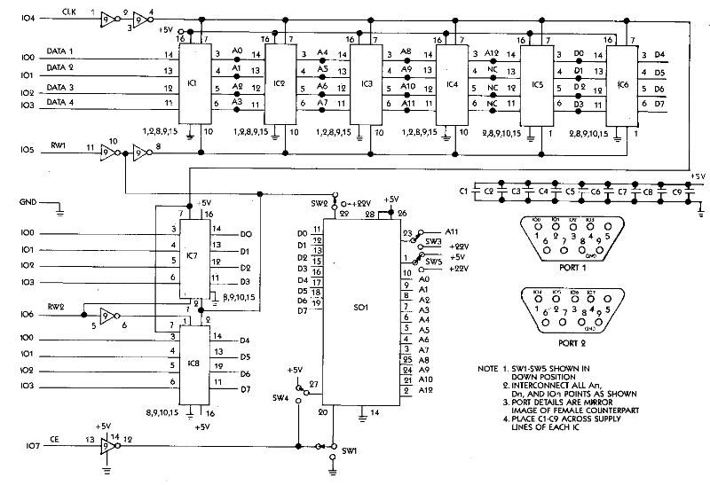
The majority of the EPROG circuitry (see Figure 1)
consists of IC1 thru IC8 which are 4-bit tri-state D-latches. Port 1 does
data transfer 4 bits at a time. The 4 bits of Port 2 are used as control
signals. IC9 is used as a buffer and signal inverter. The five mode switches
SW1 thru SW5 are used to select programming requirements for the three
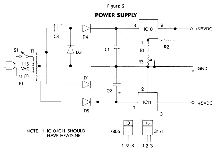
different devices. We also need a power supply to provide +5 volts and
+ 22 volts.
BUILDING AND USING EPROG
by Charles Cherry
When Antic received EPROG, we knew immediately we wanted to publish it. We were sure it functioned properly for its designer; Larry Woodgeard, but we wanted to make sure our readers could build and operate it. We asked Charles Cherry, whom we knew to have the technical background for this kind of project, to build the EPROG from scratch and describe his experience-and the pitfalls. -ANTIC ED.
The first thing you should notice about this project is that it plugs
into the wall. This means dangerous voltages are present so it should be
built and used with proper caution.
The second thing to note is there are no buffers or isolators
between the EPROG and your Atari. So when you get it assembled and are
ready to test it for the first time, you might unplug your RAMdisk, 80-column
card and other custom hardware. Chances are everything will work fine,
but if you make a mistake you could damage the computer.
Fiqure 3
PARTS LIST
IC1-IC8.........................SN74LS173
IC9..............................MM74Cl4N
SW1-SW.............SPDT SWITCHES (275-625)
Cl-C9.........0.1 MF CAPACITORS (272-1069)
MISCELLANEOUS
8ea....16 PIN WIRE-WRAP SOCKETS (276-1998)
1ea....14 PIN WIRE-WRAP SOCKETS (276-1993)
1ea...............IC BREADBOARD (276-1394)
2ea..............JOYSTICK CORDS (276-1537)
1ea......................28 PIN ZIF SOCKET
etc.......................................
POWER SUPPLY PARTS LIST
T1........24VAC CT 450MA XFORMER (273-1366)
IC10...........317T IC REGULATOR (276-1778)
IC11...........7805 IC REGULATOR (276-1770)
C2...1500MF 16V CAPACITOR (use two 272-958)
C1,C3........220MF 35V CAPACITOR (272-1029)
D1-D4...............1N4001 DIODE (276-1101)
S1 ............SPST 25OVAC SWITCH (275-602)
F1.....................1AGX FUSE (270-1271)
R2.........240 OHM 1/4W RESISTOR (271-1313)
R1........3.6K OHM 1/4W RESISTOR (271-1328)
R3.....................1K OHM POT (271-218)
MISCELLANEOUS
2ea....................HEATSINKS (276-1366)
1ea....................LINE CORD (278-1255)
1ea...................FUSE HOLDER (270-362)
1ea......................SUITABLE ENCLOSURE
etc........................................
GETTING THE PARTS
The EPROG hardware can be built on a breadboard, but for greater permanence,
I chose a perf board. All parts except the chips and the ZIF (Zero Insertion
Force) socket are available from Radio Shack. (Radio Shack part numbers
are in parentheses on the Parts List-See Figure 3.).
The chips and socket can be obtained from most mail order
companies (e.g. Jameco Electronics, 1355 Shoreway Road, Belmont, CA 94002).
You can save a whole lot of money if you shop around for the parts. I was
in a hurry so I spent about $60. You should be able to cut that in half.
This was the first IC project I ever built without a printed
circuit board. I hope you can learn from my mistakes. Since I had no wire-wrap
experience or tools, I decided on point-to-point soldering using some 22-gauge
wire I had in my kit. A big mistake. It can be done, but it ain't easy.
When I got finished, the thing did not work.
So I rebuilt it using wire wrap. It still did not work,
but it was easier to check the wiring.
After hours of brain numbing trouble-shooting, designer
Larry Woodgeard, discovered that the slide switches I had scrounged were
make-before-break types and they blew the chips during switching.
Pitfalls 1 & 2: Use wire wrap, and be certain that
you use break-before-make switches.
THE SCHEMATIC
Study the schematic (Figure 1) carefully before you lay out the board.
Notice that the wires from joystick port 1 go to IC1 and the wires from
joystick port 2 go to IC9. Look at the way IC9 (which is scattered around
the schematic) is connected. Note that IC9 is a CMOS chip and must be handled
with appropriate safeguards against static discharges.
Install the sockets and switches, but do not install the
chips until the circuit has been tested. If you're smarter than I was,
you'll get some of those labels which slide onto the sockets and identify
the pins. Lay in the + 5V and ground busses and connect them. Then install
capacitors Cl-C9 as close as possible to the power supply pins on the ICs.
Now, methodically connect all the pins, starting with
IC 1-be sure to check and recheck each hookup. Notice that pin 8 on IC9
connects to pin 10 on IC1-IC4, but it connects to pin 1 on IC5 and IC6.
Conversely, pin 1 on IC1-IC4 and pin 10 on IC5 and IC6 go to ground.
Be very patient and don't try to do it all in one sitting.
Use a low wattage iron (25 W or so), the smallest tip you can find, and
your best technique. If you have trouble translating the diagram into real
circuits, find someone who can read schematics to help you. It can be very
difficult to troubleshoot an IC circuit, so take the time to get it right
the first time.
WHERE THERE'S SMOKE...
When you have wired the EPROG, install the power supply (see Figure
2). Any supply which delivers + 5VDC @ 300 ma. and + 22VDC @ 100 ma.
will do. The diagrammed one is simple and works. You will need a voltmeter
to adjust the output by tweaking R3.
When you get the proper voltages, connect the power supply
to the EPROG circuitry. Then power up and let it run for a while. Flip
all the switches to see if anything heats up or smokes.
Everything okay? Turn off the power and double-check your
wiring one more time. Now, flip all the switches down and install the chips.
Again be careful with IC9-it's a CMOS, so be sure and ground yourself to
avoid stray static. Put in an EPROM, turn the power on-without plugging
into your computer-and check for hot ICs or smoke. Flip all the switches
again. If it still seems okay, plug in the Atari and run the program. Good
luck!
BURNING THE CHIP
The EPROG software is designed to program the EPROM from code in a
fixed buffer and to read the EPROM back into the same buffer. Buffer location
depends on the type of EPROM used. The buffer for the 2716 is $8800 to
$8FFF, the 2732 buffer is $8000 to $8FFF, and the 2764 buffer is $7000
to $8FFF.
EPROG must be used with a debugger or monitor, so after
you've typed in, assembled, and created your object file, use your debugger
to load EPROG and type "Go $6000".
The program will prompt you for chip number, read or write,
and switch configuration. Following the screen prompts, read the EPROM,
then return to the debugger and display the EPROM buffer area. If the EPROM
is unprogrammed (or erased) -the buffer will be all FFs. If the EPROM has
not been erased, it cannot be programmed. Either replace it, or erase it
with ultra-violet light, as mentioned previously.
Load or relocate the code you want to burn onto the EPROM.
When the code is in the proper buffer call EPROG again with "Go $6000"
and program the chip.
My debugger is BUG/65, from Optimized Systems Software,
and I had to make one modification. The EPROG program cycle ends with a
BRK instruction. Most debuggers regain control at this point, but not BUG/65.
Instead I changed the final instruction to RTS and used "U 6000" (user)
to call EPROG.
MAKING CARTRIDGES
When venturing forth into new territories it is always wise to get
an expert guide. So I went over to American TV (15338 Inverness Street,
San Leandro, CA 94577) for advice about making cartridges. The Atari 16K
cartridge uses ROM chips which are compatible with the 2764. All you have
to do is plug your EPROMs into the sockets.
However the 8K Atari cartridges were designed for 2532
compatible ROMs, which EPROG cannot program. Luckily, there are modification
boards for these cartridges which allow you to use 2732s. American TV has
all of these cartridges, boards, kits and instructions available.
If you want to delve into the mysteries of operating system
modification, the people to contact are Newell Industries (3340 Nothingham
Lane, Plano, TX 75074). They make the RAMrod board which will take 2732
EPROMs on the Atari 800 and 400. However the XL/XE RAMrod board uses 27128s.
If you have an XL/XE you will have to fabricate your own EPROM board.
This is an exciting and challenging project. If you are
experienced with digital circuits or can find someone to assist you, give
it a try.
Listing 1
EPROG.M65
On Antic Disk EPROG.OBJ