MOVING MISSILES IN BASIC
16K Cassette or Disk
by Tom Hudson
Last issue, I presented a machine-language subroutine which enabled BASIC programmers to move players around on the screen quickly. Shortly after the issue was sent to readers, I received a letter from Jeff Stefanski (see the Reader Comment section of this issue). Jeff asked for a modification to allow the subroutine to move missiles as well.
Rather than modify the existing player movement subroutine, I decided to write a new, stand-alone missile movement subroutine. It can be used by itself if only missiles are desired, or can be used in conjunction with the player mover from A.N.A.L.O.G. #10 if both players and missiles are needed.
Following this article are two listings. The first is a BASIC program which demonstrates the use of the missile movement subroutine. The second listing is the fully documented assembler source code for the subroutine.
What Are Missiles?
Hidden deep inside each ATARI computer is a mysterious graphics ability known as player-missile graphics. These graphics work with any graphics mode, and can be moved around on the screen without disturbing any other graphics. Why are these graphics called players and missiles? PLAYERS are eight pixels (picture elements) wide and therefore can be used to create fairly detailed images, such as spaceships, cars, or other animated figures representing the player.
MISSILES, on the other hand, are only TWO pixels wide. They were designed to be used as simple projectiles, because of their limited resolution.
The Demonstration Program
Enter Listing 1 into your computer. Before running it, be sure to SAVE it, as a mistake in typing the assembly-language code could lock-up your computer, making it necessary to re-enter the program. When RUN, this program will place the numbers 1-4 on the screen using the four missiles and move them around randomly. Lets walk through the program and see what each line does.
Line 200 - This line loads the machine-language missile movement subroutine into a string called MISMOV$. This subroutine will be called whenever we want to move a missile on the screen.
Line 240 - This line sets up four string variables, M0$ through M3$. These strings will hold missile shape data. These strings are currently set up as 6 bytes long, which limits the missile graphics images to 6 pixels in height. You can change this length to up to 128 bytes, making the missile image 128 pixels high.
Lines 250-280 - These lines READ the DATA in lines 690-750 into the missile shape strings set up in line 240. Once again, note that each line reads 6 bytes into the appropriate string. To make missile images of different height, change the 6 to the desired value.
Lines 290-320 -These lines set up the player-missile area in memory and activate them. Line 320 sets the player-missile priority to 1. This causes the players and missiles to appear in front of other graphics. These lines should not be changed.
Lines 330-360 - Since there is no SETCOLOR command for player-missile
graphics, we must POKE the appropriate color values into the P/M color
registers. To get the color number, use the formula:
COLOR POKE VALUE = (COLOR NUMBER *16) + BRIGHTNESS
Line 370 - Sets the background color to black.
Line 410 - Dimensions two arrays, X and Y. These arrays will be used to hold the X and Y coordinates of each missile.
Line 420 - This line initializes all the missiles X coordinates to 128 and the Y coordinates to 64. These coordinates will place the missiles at the center of the screen.
Line 430 - This line starts a FOR-NEXT loop which will process each missile, from missile 0 to missile 3.
Lines 440-490 - These lines randomly change the X and Y coordinates of the missiles, which will make them wander around on the screen.
Line 500 - Depending on the missile number (I) this line transfers control to the appropriate USR statement in order to move the desired missile.
Lines 510-540 - These lines send the X and Y coordinate information to the
missile movement subroutine. Line 510 moves missile 0, 520 moves missile 1, etc.
Lets look at line 510:
A=USR(MISL,0,PMB,ADR(M0$),X(0),Y(0),6):GOTO 50
This statement has 7 parameters inside the USR parentheses.
MISL is set up in line 200. Do not change this variable. It is the address of the missile mover subroutine.
0 means we want to move missile zero. Note that line 520 has a 1 here, since it moves missile 1. This value can range from 0 to 3, and will move the appropriate missile.
PMB is the player-missile base address, which was calculated in line 300. Do not change this variable.
ADR(M0$) tells the missile mover where to get the missile image data. In this case, we want the subroutine to use the information in the string variable M0$. Try changing this to ADR(M1$) and RUN the program. You will see two 2's moving on the screen. This is because the string M1$ contains the data for the number 2, and it is now used in both missile 0 and missile 1.
X(0) is the X coordinate where we want to place missile 0. You can place any number or variable here, ranging from 0-255.
Y(0) is the Y coordinate where we want to place missile 0. You can place any number or variable here, ranging from 0-127.
6 tells the subroutine how many bytes are used for the player image. In this case our missiles are 6 bytes long (see lines 240, 250, and 690). If you want a different number of bytes (resulting in a different missile height), change these lines accordingly.
Line 550 - This line completes the FOR-NEXT loop set up in line 430.
Line 560 - This line passes control to line 430, causing the program to loop forever, moving the missiles randomly until you press the BREAK key.
Lines 600-640 - These lines contain the DATA for the missile mover routine. Do not change these values.
Line 690 - DATA for M0$, the number 1.
Line 710 - DATA for Ml$, the number 2.
Line 730 -DATA for M2$, the number 3.
Line 750 - DATA for M3$, the number 4.
Creating Your Own Missile Images
Now, that we have walked through the program and studied what each line does, lets design our own missile image. Since were limited to 2 pixels in width, the image will have to be very simple. Of course, it can be any height up to 128 pixels.
The numbers that the demonstration program moved around on the screen are
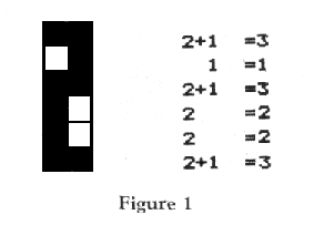
very simple. Figure 1 shows how the number 2 was turned into DATA in line 710.
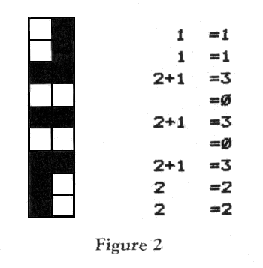
The shape we will make is shown in Figure 2.
Now lets put our shape into demonstration program. Well use missile number 0
to show the image, so replace line 690 with the following:
690 DATA 1,1,3,0,3,0,3,2,2
This missile image is 9 bytes long, so it will be necessary to change lines 240, 250 and 510 as follows:
240 DIM M0$(9),M1$(6),M2$(6),M3$(6)
250 FOR I=1 TO 9:READ N:M0$(I)=CHR$(N):NEXT I:REM *** MISSLE 0 ***
510 A=USR(MISL,0,PMB,ADR(M0$),X(0),Y(0),9):GOTO550
After the program is changed, RUN it. You will see the numbers 2, 3, and 4 on the screen, along with the shape we just defined. Its that simple!
Summary
Using players and missiles in BASIC can be very fast and easy when a machine-language subroutine is used to perform time consuming operations. This demonstration program may be used as a framework for more complex programs. Simply replace lines 410-560 with your own program code, and youre all set to begin exploring the wonders of player-missile graphics!
If you have any questions or suggestions about this article write me care of A.N.A.L.O.G. Be sure to include a pre-addressed, stamped envelope if you would like a reply.
I would like to thank Jeff Stefanski for his suggestion that a missle movement subroutine be written for A.N.A.L.O.G. Computing. If you have any suggestions for articles, just write.