Be patient!
this site is being under construction, or rather major reconstruction. if something looks odd, or doesn't work, it's probably because i'm editing something
Sites

Running a site costs, so if You think it is important to continue my work and keep this site and programmer's software alive and updated frequently, feel free to donate via PayPal service
Hardware
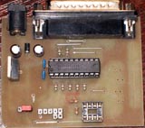 Basically it is Altera ByteBlaster II interface with added socket and 3v3 regulator for power supply to the device. In future i'll add willem/ezo hardware support... Schematics and PCB layout for in download section.
Schematics and pcb layout:
![]() Schematics
Schematics
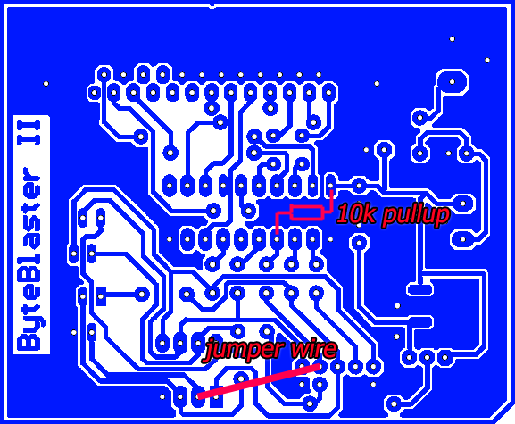
For improoved compatibility with MX and SST device fafmilies do the following modification:
Cut the trace leading to pin #20 of 74hct244 chip, reconnect it using jumper wire with pin #8 of 25xx DIP8 socket
Start with connecting the programmer to regulated power supply (anything that gives 8-15V DC will be OK, current consumption of programmer and programmed device is marginal).
Download Parallel port monitor freeware from Geek's hideout web page and run it.
toggle pin 7 - D5 - pin 10 should change its state
toggle pin 9 - D7 - pin 12 should change also its state
pin 13 and 15 should be green when hardware is connected, but might be
diffrent if any chips are put into the socket
if this test passes, then you've working hardware, and should not worry
about the "hardware not present" issue
